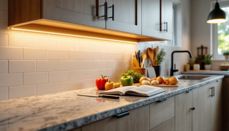
Adding under cabinet lighting transforms a kitchen from functional to exceptional. The task strips, LED pucks, and linear fixtures illuminate countertops where you prep, chop, and cook, eliminating shadows cast by overhead lights and adding both safety and visual appeal. While plug-in options exist, hardwiring your lights delivers a cleaner look without visible cords or countertop clutter. This guide walks through planning, wiring, and connecting under cabinet lighting directly to your home’s electrical system. Fair warning: this project involves working with live circuits, so if you’re uncomfortable with electrical work or local codes require a licensed electrician, don’t hesitate to call a pro.
Table of Contents
ToggleKey Takeaways
- Hardwiring under cabinet lighting eliminates shadows and clutter while providing superior task lighting compared to plug-in alternatives.
- Choose between 120V linear fixtures (simplest to wire), low-voltage LED strips (safest, requires a transformer), or puck lights based on your kitchen layout and wiring comfort level.
- Plan your circuit carefully by measuring cabinet footage, calculating total wattage, and confirming your breaker has capacity while staying below 80% per NEC requirements.
- Always turn off power at the breaker, use a non-contact voltage tester twice, and secure all wire splices in approved junction boxes to meet electrical code.
- Daisy-chain 120V fixtures by connecting black-to-black, white-to-white, and ground-to-ground at each location, then test connections before permanently securing covers.
- Verify your local electrical code, obtain permits if required, and consider hiring a licensed electrician if you’re uncomfortable working with live circuits.
Understanding Your Under Cabinet Lighting Options
Before running wire, decide which fixture type fits your kitchen layout and style. The three most common options each have distinct wiring requirements.
LED strip lights offer flexible installation, they’re thin, low-profile, and can bend around corners. Most draw 12V or 24V DC, requiring a transformer (driver) that steps down 120V household current. The driver typically mounts inside a cabinet or in a basement/attic space, with low-voltage wire running to each strip section.
Puck lights are individual disc-shaped fixtures spaced along the cabinet run. They work well for spot lighting but can create uneven illumination if spaced too far apart. Available in both 120V AC and low-voltage versions, 120V pucks wire together in a daisy-chain while low-voltage models need a transformer.
Linear hardwired fixtures (also called light bars) mount end-to-end beneath cabinets and typically run on 120V AC. They’re the simplest to wire, just like wiring a series of ceiling lights, and provide the most uniform task lighting without hot spots.
Most DIYers find 120V linear fixtures or low-voltage LED strips easiest to install under cabinet lighting because both systems accommodate linking multiple units. Low-voltage options add a safety buffer: if you nick a wire during installation, 12V won’t deliver a dangerous shock the way 120V can.
Essential Tools and Materials You’ll Need
Gather everything before you start. Missing a connector mid-project means an extra trip to the hardware store with cabinets half-disassembled.
Tools:
• Non-contact voltage tester – confirms circuits are dead before you touch any wires
• Wire strippers and wire cutters
• Screwdrivers (Phillips and flathead)
• Drill/driver with bits for wood and drywall
• Fish tape or pull wire if running cable through walls
• Stud finder to locate joists and avoid plumbing/ductwork
• Level for aligning fixtures
Materials:
• Under cabinet light fixtures (linear bars, pucks, or LED strips)
• 14/2 NM-B (Romex) cable for 120V runs, or appropriate low-voltage wire if using a transformer
• Wire connectors (wire nuts)
• Cable staples or plastic-sheathed clamps
• Electrical boxes (if code requires, or using existing switch box)
• Transformer/driver (for low-voltage systems)
• Junction box if splitting power to multiple fixtures
Safety Gear:
• Safety glasses
• Work gloves
• Dust mask if drilling into drywall or cabinets
Double-check your local electrical code. Some jurisdictions require metal-clad cable (MC) instead of Romex in exposed areas, and most require all connections inside approved junction boxes.
Planning Your Lighting Layout and Circuit
Measure the total linear footage of cabinets you’re lighting. For task lighting, aim for continuous or near-continuous coverage, gaps longer than 12 inches create dark zones that defeat the purpose.
Calculate total wattage: add up the wattage of all fixtures. Most LED under cabinet lights draw 5–10 watts per linear foot. A typical 15-amp kitchen circuit can handle 1,800 watts (15A × 120V), but the National Electrical Code (NEC) requires you stay below 80% of capacity for continuous loads, so 1,440 watts max. Under cabinet lighting rarely approaches that limit, but if you’re tying into an existing circuit that also feeds outlets or other lights, confirm the circuit has capacity.
Choosing a Power Source:
You have three options:
- Tap an existing switch box that controls overhead lights, this lets one switch control both overhead and under cabinet fixtures simultaneously.
- Add a dedicated switch by running new cable from the breaker panel (or tapping an existing junction box) to a new switch location, then to the lights.
- Wire directly to an always-hot circuit and use individual fixture switches or a wireless remote/smart switch module.
Option 2 is most common for retrofits. It also ensures your over sink kitchen lighting and under cabinet system don’t overload one switch.
Routing the Cable:
Ideally, fish cable through the wall cavity behind cabinets and down to a switch box. If cabinets sit against an exterior wall or routing is impossible, you can run cable through the back of the cabinets themselves (check local code, some inspectors frown on cable inside cabinetry). For island or peninsula cabinets with no wall access, you may need to route through the basement or crawlspace below.
Map your run on paper: mark the breaker or junction box, switch location, and each fixture. This plan helps when you’re elbows-deep in a cabinet, trying to remember which wire goes where.
Step-by-Step Wiring Instructions
Hardwiring to Your Electrical System
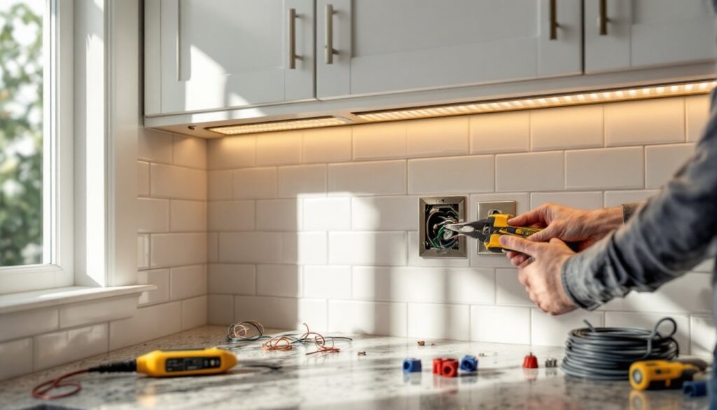
1. Turn off power at the breaker. Use your non-contact voltage tester on the circuit you’ll be tapping. Test twice, once at the breaker panel and again at the switch or outlet box. According to This Old House, even experienced electricians double-check before touching wires.
2. Install the switch box (if adding a new switch). Cut a hole in the drywall using a remodel (old-work) electrical box template. Mount the box, securing it with built-in clamps or screws to the stud if one is nearby.
3. Run cable from power source to switch. If tapping an existing hot circuit, open that box and splice into the hot (black) and neutral (white) wires using wire nuts. Secure the new cable with a cable clamp entering the box. Run 14/2 NM-B to your new switch location. Staple cable every 4½ feet and within 8 inches of any box per NEC Article 334.
4. Run cable from switch to first light fixture location. Fish it through the wall or along the cabinet backs. Leave at least 8 inches of wire extending from each box or fixture location for connections, you can always trim excess, but you can’t add length without a junction box splice.
5. Prep and strip wires. Strip ½ inch of insulation from each conductor. If your fixtures have push-in connectors, follow the manufacturer’s strip length (usually ½ to ⅝ inch).
6. Wire the switch. Connect the incoming hot (black) wire to one brass terminal, and the outgoing hot (black wire going to lights) to the other brass terminal. Twist the two neutral (white) wires together with a wire nut, they bypass the switch. Pigtail the ground wires (bare copper) together and connect one tail to the green ground screw on the switch. Fold wires neatly into the box and screw the switch to the box ears.
7. Wire the first fixture. Most 120V linear fixtures have a black (hot), white (neutral), and green or bare (ground) wire. Match colors: black to black, white to white, ground to ground, securing each with a wire nut or the fixture’s built-in connectors. If using low-voltage LED strips, the transformer typically has screw terminals or wire leads, connect the 120V input side the same way, then run low-voltage wire from the transformer output to the LED strips.
Connecting Multiple Light Fixtures
1. Daisy-chain 120V fixtures. After wiring the first fixture, run a new length of 14/2 NM-B cable from its junction box (or built-in wire compartment) to the next fixture location. At each fixture, you’ll have two cables entering: one from the upstream power source, one continuing to the next fixture downstream. Connect all blacks together (incoming, outgoing, and fixture lead), all whites together, and all grounds together using appropriately sized wire nuts.
2. For low-voltage strips, use parallel wiring. Run individual low-voltage wires from the transformer to each strip section or use connectors designed for daisy-chaining LED strips. Check the transformer’s maximum load, common drivers handle 60W to 100W total. If your combined strip wattage exceeds that, use a second transformer on a separate circuit or segment.
3. Secure all connections inside junction boxes. The NEC (Article 300.15) requires all splices to be accessible and contained in approved enclosures. If you’re connecting several runs, install a metal or plastic junction box in the cabinet or wall cavity. Some linear fixtures have large enough wire compartments to serve as junction boxes, check labeling.
4. Strain-relief and cable management. Use cable staples on wood surfaces or zip ties inside metal cabinets to prevent wires from sagging or snagging. Leave a small service loop (a few extra inches of wire coiled neatly) at each fixture to allow future removal without re-running cable.
5. Label wires. If you’re installing under an island with multiple fixture zones, wrap a small piece of tape around each cable and write its destination (“left side,” “right side,” “island west”) before making final connections. Future you, or the next owner, will thank you.
Testing and Troubleshooting Your Installation
Before securing fixtures permanently, test the circuit.
1. Restore power at the breaker. Leave fixture covers or lenses off so you can see inside if needed.
2. Flip the switch. If lights illuminate, you’re 90% done. If nothing happens, turn the breaker back off immediately and recheck connections. Common issues include:
• Loose wire nut – a single strand outside the connector can prevent contact.
• Reversed hot/neutral at the switch – the switch must interrupt the hot wire, not the neutral.
• Tripped GFCI or AFCI upstream – some kitchen circuits have GFCI protection: a wiring fault will trip the outlet. Reset and retest.
3. Check for flickering or dimming. If lights flicker, inspect each wire nut, backstab connections can work loose. If lights dim when other appliances run, the circuit may be overloaded: consult an electrician about adding a dedicated circuit.
4. Verify uniform brightness. Uneven lighting in LED strips often indicates voltage drop over long runs. For low-voltage systems, limit runs to 16–20 feet per transformer output, or use higher-gauge wire (thicker, e.g., 18AWG instead of 22AWG).
5. Final inspection. Once everything works, turn off power again. Tuck wires neatly, secure all cable runs, and install fixture covers and lenses. Snap lens covers into place, most use spring clips or slide-in tabs. Restore power and enjoy shadow-free countertops.
Building Code Note: Many jurisdictions require an electrical permit for new circuits or modifications to existing branch wiring. The permit process typically includes an inspection before drywall is closed and after fixtures are installed. Budget an extra day or two for scheduling if permits apply in your area. According to Family Handyman, working without a required permit can complicate insurance claims or home sales.
If you’re adding kitchen lighting over island fixtures in the same project, wire them on the same circuit for coordinated control, or separate them if you want independent dimming. Either way, keep total wattage below your circuit’s safe capacity, and document your layout with a simple sketch tucked inside the breaker panel door for future reference.